")
Tight new fibre-optic testing limits needed for higher bandwidth apps
With the ratification of 40 and 100 Gbps ethernet fibre standards, optical requirements are tighter than ever before - yet fibre testing methods have not been upgraded for many years. Consider, too, that with the introduction of 10 Gbps over ethernet, the maximum power loss budget for multimode fibre links has dropped significantly, and it is clear that changes in testing standards are essential and urgent.
While an accuracy of 0.5 to 1 dB might have been tolerable in the past, it is not acceptable with 10 Gbps or higher, especially as the demand for 1.5 dB maximum power loss with OM4 fibres for 40 and 100 Gbps applications requires precise test equipment and test procedures.

ISO/IEC 14763-3 was launched in 2006, with amendments added in 2010, in order to reflect the new tighter budget in test methods and equipment. The major changes are:
- Launch and tail test cords with controlled end-faces
- Reference connectors with very low loss
- 1- and 3-test cord methods for reference setting with LSPM devices
- 2-test cord methods are not acceptable
- Introduction of encircled flux for accuracy of multimode light source
- Detailed procedures for LSPM and OTDR devices
The main reason for all these changes is accuracy and reliability. With a budget of 1.5 dB for 40/100 Gbps, a test tolerance of 1 dB is not acceptable and testing with outdated or inaccurate equipment/methods doesn’t make sense.
The introduction of reference test cords with reference connectors is a mandatory step for reliable results, since only reference test cords and connectors guarantee tight tolerances and comparability. This means that commercial fibre patch cords for testing are no longer allowed for good reasons.
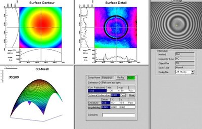
A second major step is the geometry of the polished end-face. With modern polishing technologies and 3D analysing in the factory, those test leads guarantee precise geometry when they are utilised.
The test methods for LSPM devices have been reworked in order to cover the current generation of testers on the market and practical situations in the field. The 1-test cord method can be used if the tester has a changeable interface or the installed fibre cable link and the reference test cords have the same interface. Otherwise, the 3-test cord method should be used. This method is independent of the tester and allows any adaption of installed connectors. A big benefit for the installer is the ability to measure the exact installed link.
In the end, both 1 and 3-test cord methods of reference setting provide standards-compliant results.
Another important step is the introduction of encircled flux for multimode testing. In the past, the following phenomenon has been seen: the same link measured with different testers and all results differ significantly. The reason is the light characteristic of LED and VCSEL light sources. Multimode transmission is much more complicated than singlemode. The energy distribution of the modes is different with each light source, resulting in variances of the test results.
This explains the different results in the past. The worst case is an OTDR with a laser source, where all energy is in the centre part of the fibre core. This frequently produces different (usually more optimistic or artificially better) results than LSPM testers or real-life multimode sources in switches.
The encircled flux method of conditioning the light distribution within a multimode core of the launch test cord is currently considered the most accurate way of launch delivery.
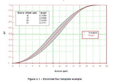
Encircled flux is the percentage of power within a given fibre core radius. The defined template, Figure A.1, ensures consistent light source conditions and therefore more accurate and repeatable results.
The current dilemma is the non-existing definition of light sources within LSPM testers. If all test equipment used defined and categorised light sources, the test results would be more consistent. External EF controllers must be used to control the light conditions unless the LSPM tester manufacturer certifies that its equipment meets current EF requirements at the test cord end-face and is calibrated each year. The use of mandrels now needs to be replaced by EF modcon test leads complete with reference connectors.
All necessary equipment is becoming available in test kits which contain EF test cords for multimode LSPM or longer reference launch and tail test cords for OTDR devices.
OTDR
The OTDR is another recognised test device and has been used for many years around the world. However, the typical area of application is the WAN or MAN. Due to short distances and usability issues, the OTDR is not recommended in LANs, and in many cases is not allowed in the case of systems warranty submissions.
The biggest advantage of an OTDR is the ability to see the installed link on a trace. The OTDR is able to show each part of the link as all components have a typical reflection. The attenuation is shown as a declining curve while an interconnection generates a peak and a declining curve.

Compared to a power meter, the OTDR is able to measure an optical value which has gained more importance over the years in the LAN area - return loss. Each interconnection causes a reflection and there is an unwanted loss of the optical signal. Return loss is a common parameter in the telecoms area. A bad return loss may cause high reflections and is able to destroy the expensive lasers used in this environment. High-end interconnections have about 65 dB return loss.
In LAN multimode areas, return loss can be controlled in the production phase and as such is not a required field testing parameter. A high-end multimode interconnection has a return loss of 35 dB, while the standard requires at least 20 dB.
Cleaning
With a budget of 1.5 dB for 40/100 Gbps ethernet, any dust or contaminants at the end-face may result in a non-functional channel. For many years, cleaning and inspection of end-faces has been compulsory before connectors are used, even for brand new cables. Most faults in the field are based on dirt or contaminated end-faces or missing test equipment.
Therefore, cleaning equipment is a must for the installer or operator. This applies to all connectors, be it in the bulkhead or the end of a patch cord. Cleaning becomes extremely important with the introduction of multicore connector end-faces, such as MPO systems.
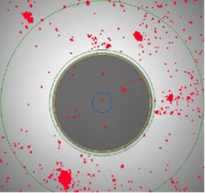
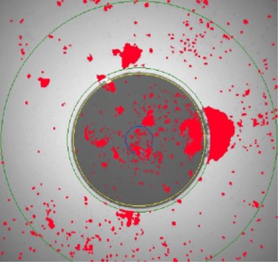
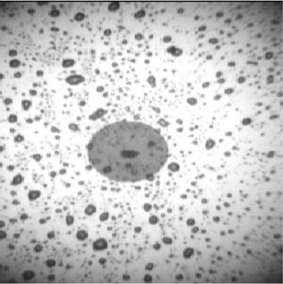
Cleanliness of all connector interfaces and special test cables and/or reference plug connectors is important in obtaining correct, repeatable and reproducible results. With small core diameters of 9 or 50 µm, the smallest particles on a connector surface can disturb and affect the result. The often practised quick wipe on clothing can lead to the surface appearance detailed in Figure 1, so special lint-free cloths or alcohol wipes should be used for cleaning.
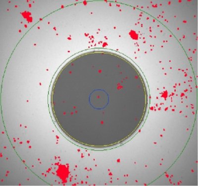
The importance of a clean end-face is shown in the pictures below. Two connectors have been mated one, two and five times. Each time, more dust is collected and even more critical are the dust particles moving towards the core. These have a deep impact for 1 and 10 Gbps channel testing. As ISO/IEC 11801 has defined, any small particles of dirt or contaminants may see failure of the link during both testing and operation phases.
Dust particles might have a strong influence on the connector attenuation and return loss as it disturbs the physical contact between the fibre cores.
Always check if end-faces are clean before connecting connectors to each other, and after every re-patching also first check if end-faces are clean. Always remove dust and dirt, and after removal check again.
Always make sure that the transmitter is turned off or there is no network connection before inspection. (Always pay attention/be careful when using a microscope.) Safety when looking at fibre end-faces is paramount. The use of video probes avoids the risk of direct exposure to the user’s eyes.

Conclusion
The information above summarises the need for accurate and precise fibre-optic testing. There are new, tight limits required for fibre to suit the new higher bandwidth applications.
Installers, consultants and end users need to be aware that these standards will impact on the testing set-up. Up-to-date, regular maintenance and calibration of the test equipment with more precise reference test cords comes at a price. On the other hand, troubleshooting is very easy if the test equipment is in a healthy condition. Many field problems such as gains or high loss occur due to bad test cords and test equipment.
In addition to ensuring that test equipment is up to standard, it is important to ensure that multimode and singlemode fibre testing is done according with ISO/IEC 14763-3.
The climate risks of future tech
Will large-scale technology developments such as AI-driven systems and electrified homes create a...
Efficient HVAC protects Aussie hospital during bushfires
Maintaining excellent air quality in a hospital during bushfire season is a challenge —...
Network provider opts for unified cybersecurity platform
A major cyber incident could disrupt essential services and affect communities statewide, as well...


