")
Surge protection - the what, how and why
Friday, 30 September, 2011
There are various terms used to describe surge protective devices (SPDs), such as arrestors, lightning arrestors, surge arrestors, transient voltage surge suppressors (TVSS), surge diverters and surge protectors. The term surge filter or surge reduction filter usually refers to a series surge protector. However, all series-connected SPDs are not surge reduction filters. This article will explain the purpose and the operation of SPDs and the key selection criterion for selecting and specifying an SPD.
Shunt surge protection
The most common type of SPD is shunt connected. There are various types of SPDs, including metal oxide varistors (MOVs), silicone diodes, gas arrestors, spark gaps and triggered spark gaps. All of these are connected in shunt configuration, and no one device type is considered superior over the other. All of the devices have advantages and disadvantages that need to be considered for each application.
Figure 1 below shows an MOV connected in a shunt configuration between active and neutral.
|
|
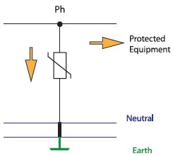
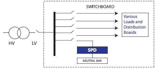
Figure 2 shows how the SPD is connected in a switchboard. It is in parallel with other loads and hence it gets its name shunt-connected SPD.
|
|
In a shunt application, a surge diverter is installed between supply active and neutral and between neutral and earth. Most MOV-based shunt surge diverters clamp at a certain voltage, which is above the supply voltage. Typically, surge diverters have a clamp voltage of above 275 V for a 240 V system. They switch on at the clamp voltage and momentarily create a short circuit to ground to allow the surge energy to divert to the ground instead of going to the load. Lightning surges and other power system transients are extremely fast and can have very high amplitudes. Therefore, to be effective, surge diverters need to switch on quickly and handle large amounts of energy in a short time. When chosen correctly, upstream circuit breakers or fuses do not get time to trip in the event of the surge diverter activating because the reaction time of circuit breakers and fuses is much slower.
Test wave shapes
The test wave shapes for the testing of SPDs are defined by IEC 61643 standards. The ratings of SPDs tested using these test wave shapes is now universal and applies to most countries, including Australia and the US. In Figure 3, two current test wave shapes are shown. The test wave shapes need to be defined so that different devices can be tested in the same way and product-consistent ratings of current and voltages can be determined.
The 8/20 µs test wave shape is the most common current waveform used to define ratings of surge protection devices. It is defined in many international standards. Under this test wave shape, the current rises from 10% of peak to 90% of peak in 8 microseconds and falls to 50% of peak in 20 microseconds.
|
|

The user may not need to worry about the technicalities of these waveforms but does need to know that when choosing a surge protection device it is rated based on these waveforms. For example, you can get an SPD rated at 100 kA based on the 8/20 µs waveform. It does not make much sense if you just said 100 kA as a different waveform will produce a different kA. There is another current waveform called the 10/350 µs, which is similar to the above waveform but has a longer tail. A device with 100 kA rating on 8/20 waveform may only have a rating of 10-20 kA on a 10/350 waveform.
Figure 4 shows a voltage test waveform that is commonly used to test surge protection devices. In the voltage waveform, the voltage rises from 30% of peak to 90% of peak in 1.2 microseconds and falls to 50% of peak voltage in 50 microseconds.
|
|

Key performance parameters of an SPD per IEC61643
Various performance measurements are written in the specification sheets or nameplates of SPDs. This section will discuss and explain the six key performance yardsticks that can be used in making the appropriate selection of SPDs. All but one of these performance parameters are well defined and discussed by IEC61643 standards and now are included in the AS/NZS1768-2007 Lightning Protection Standard.
These are: maximum discharge current, or Imax; nominal discharge current, or In; voltage protection level, or Up; maximum continuous operating voltage, or Uc; maximum impulse current, or Iimp; and, voltage rise time, or dv/dt.
Maximum discharge current (Imax)
The Imax gives an indication of the amount of surge energy the SPD will be able to handle without getting damaged. The Imax is often equated to the maximum single shot current the SPD can handle. However, the testing done under IEC standards involves several impulses before applying full Imax.
The current and the voltage of the wave shapes at which this Imax is applied are defined by IEC standards. Imax is tested using the 8/20 µs current wave shape.
Nominal discharge current (In)
In is an indication of the nominal current the device will need to conduct in its lifetime. A common misunderstanding is that SPDs are only good for one shot of a lightning surge. However, there are many devices available that may withstand thousands if not tens of thousands of surges. The IEC standards require SPDs to be tested for common power system applications or Class II applications, to withstand 15 impulses at In followed by 10%, 25%, 50%, 75% and 100% of Imax. Cooling between the applications of the test wave shapes is allowed in accordance with IEC61643 Standards. In is a multiple shot rating of an SPD. Obviously an SPD with a higher In rating will withstand more surges and last longer. In is also tested using 8/20 µs current wave shape.
Maximum impulse current (Iimp)
Iimp rating is also called upon in IEC standards for Class I products. Iimp is usually used to test spark gap and triggered spark gap product, but can be used for Class I metal oxide varistor or MOV products as well. Iimp is similar to Imax, but the testing occurs using the 10/350 µs. This wave shape has a larger area under the curve and hence a lot more energy. A device with a certain Imax rating will have a lower Iimp rating. Typically for MOV devices, Iimp will be approximately 10% of Imax.
Voltage protection level (Up)
Typically, SPDs are connected between the phase and the earth, or the neutral in the case of multiple earth neutral (MEN) systems. SPDs remain open circuit at nominal voltages, but if the voltage exceeds its clamp voltage, the SPD will temporarily short out to ground. This enables the excess energy to be diverted to earth. This is perhaps the reason that SPDs are also commonly referred to as surge diverters. The Up characterises the performance of an SPD in limiting the voltage and indicates how well the SPD clamps an applied surge. An SPD with a lower Up is a better device in terms of limiting the voltage across equipment. Figure 5 shows the Up with respect to the applied standard voltage wave shape and the clamp voltage.
|
|

Up is measured at In under IEC standards and the voltage protection level can be measured at other currents. For example, in Australia they are typically tested at 3 kA. Measuring Up at a constant current allows direct comparison of let-through voltage to be made between products. A device will have a lower voltage protection level at 3 kA (8/20), or 750 V, than at 20 kA (8/20), or 1000 V.
Maximum continuous operating voltage (Uc)
SPDs are voltage-limiting devices and it is important to select an SPD that will not attempt to clamp slight overvoltages at 50 Hz. Uc is a guide to how rugged the SPD is against overvoltages. If the SPD attempts to clamp the voltage continuously, then this can result in damage to the SPD or even a fire hazard if the SPD gets hot. Overvoltages can occur due to mains voltage temporarily rising and forcing the SPD to conduct the top and bottom of every half cycle. The SPD can get into a similar type of conduction at its end of life whereby its clamp voltage drifts down. Eventually this voltage can be low enough to clamp the normal voltage.
An SPD generally has built-in thermal fusing to disconnect it at its end-of-life conduction. There is an indication circuit attached to this fusing to indicate end-of-life failure. This failure mode can also occur when the SPD has not reached its end of life but temporarily overvoltages. Some modern products have transient discriminating technology that allows the device to discriminate between surges and temporary continuous overvoltages and only get into conduction during surges.
The example below demonstrates that two SPDs which have identical Imax ratings may have starkly different In, Up and Uc. The TDS MT 277 is the better choice in this example.
|
Imax = 100 kA In = 50 kA Up = 850 V at 3 kA (8/20 µs) Up = 1700 V at 50 kA (8/20 µs) Uc = 275 V |

|
In = 80 kA Up = 750 V at 3 kA (80/20 µs) Up = 1000 V at 20 kA (8/20 µs) Uc = 480 V |

It is worth pointing out that there are several schemes that can be used for choosing installation locations of SPDs. The choice of the scheme depends on cost, the sensitivity of the equipment being protected, the frequency of the occurrence of surges, the importance of the systems or the processes being protected.
For example, a simple scheme would have an SPD with low Up and a high Imax and In at the main switchboard and no subsequent downstream protection.
In a larger installation, there may be a need to install an SPD at the main switchboard as coarse primary protection and SPDs on distribution boards as finer secondary protection.
Operation of surge reduction filters that reduce dv/dt
In critical applications, surge reduction filters (SRFs) are used as finer protection. The yardsticks described above (Imax, Iimp, In, Uc and Up) can still be used to define performance of SRFs. But other than lowering the voltage to which the equipment is exposed, the SRFs also reduce the voltage rise time, or dv/dt. It is widely recognised that sensitive electronic equipment is in danger of being damaged from large amplitudes and high rise time associated with power surges. While surge diverters or SPDs take care of the amplitude factor only, the SRFs take care of both the amplitude and the dv/dt factors.
As shown in the diagram below, the output voltage is typically reduced to approximately 300 V, while the incoming extremely high rate-of-voltage rise of 3000 to 12,000 V/µs has been reduced to 10 to 100 V/µs. This slower change in voltage is better withstood by electronic equipment using switched mode power supplies. The filter also helps to attenuate small signal RFI/EMI noise problems. The diagram also shows that a good SRF design will also have shunt surge protection on its output. This primarily helps protects against surges generated within the facility itself.
Operation on telecommunications line protectors
The telecom services considered in this article are transported on twisted pair. Each service has two wires, or lines, sometimes called the ‘a’ and ‘b’ wires. Surges can occur from each line to ground, known as L-G or common mode, or occur across the lines, known as L-L or differential mode. The surges that occur from each line to ground usually do so at the same magnitude at the same time, hence the name common mode. This is an important observation and derives from the fact that these twisted pairs are balanced, and noise signals or surge energy is coupled onto both wires equally. The receiving telecommunications equipment is looking for differential signals, and is most sensitive to noise and surges in the differential mode. That is, the telecom equipment is generally more robust against common-mode L-G signals. The following diagram illustrates the idea of a common-mode surge.
|
|

All telecom surge protectors contain primary overvoltage protection. It is the stage of protection providing the voltage-limiting function, and generally diverts the surge current to ground. This element is usually a gas arrestor, or GA.
A premium telecom surge protector will have a secondary overvoltage clamping element. This is usually configured from line to line and is either an MOV or a silicon diode. A schematic for such a device is shown below. The secondary element is generally a purpose-designed telecom protection thyristor component. These components have developed to the point where they are robust; have excellent, instant, clamping performance; feature low capacitance; and have rendered MOVs or transorb diodes obsolete in this application. The secondary L-L clamp is important since it provides protection for the damaging L-L voltages or differential mode voltages.
The series elements are needed to coordinate the operation of the primary and secondary clamping elements.
|
|

Conclusion
The electrical industry in Australia has increasingly focused its attention on surge protection. In the 1980s and 1990s, the interest in this subject was limited to the telecommunications and defence sectors. However, as electronics have begun to dominate our lifestyles and have entered our business and homes in various forms, surge protection has captured the interest of an even wider audience. At the same time, Australian and international standards on surge protection continue to develop.
By Rohit Narayan, ERICO
Upgrading electrics at the Smithsonian
The renowned US institution engaged ABB to perform a challenging upgrade of its historic Arts and...
Critical infrastructure for a mega fulfilment centre
Spanning 80,000 m2, the facility holds up to 1.6 million items, including large products like...
AEMO releases new ISP: industry responds
Formed in consultation with almost 2000 stakeholders, the 2026 Integrated System Plan confirms...


